About me

My photo
Vanløse, Copenhagen, Denmark
Mathematician. Working programmer/system developer. Nerd. Married. Father of 3.
Showing posts with label Original. Show all posts

23.4.16

NMK Thunder Dragon Repair Log

Some repairs can be very tedious and take you months (even years) of fighting with the PCB to complete. Others on the other hand can be both easy to diagnose and to repair. This is one of the latter. And I think it is important to tell about the full spectrum of difficultness. So here we go...

This little baby by NMK has actually already been on the table once before when I bought it as defective. But a couple of months ago, I decided to bring it to a cozy get-to-together with my dear friends at MadGearArcade (a private arcade set up with some candy cabs and SuperGuns in my friends living room };-P), as they all 3 love good shmups. It was just bobble wrapped and stuffed tightly into a bag-pack together 3-4 other PCBs. I know this is of cause not the optimal way of transporting arcade PCBs, but when you don't own a car and have to bike to get to your destination, and you also know how to fix brokes PCBs, this is actually how I usually transport them to different gatherings.

When I connected it in the a wonderful Sega Aero City and flipped the on-switch, I quickly discovered that something was wrong with the music and some of the sounds. Most noticeable was, that the intro music was played in level 1 instead of the normal music for that level (this video is not from that night, but shot with my tv and SuperGun).


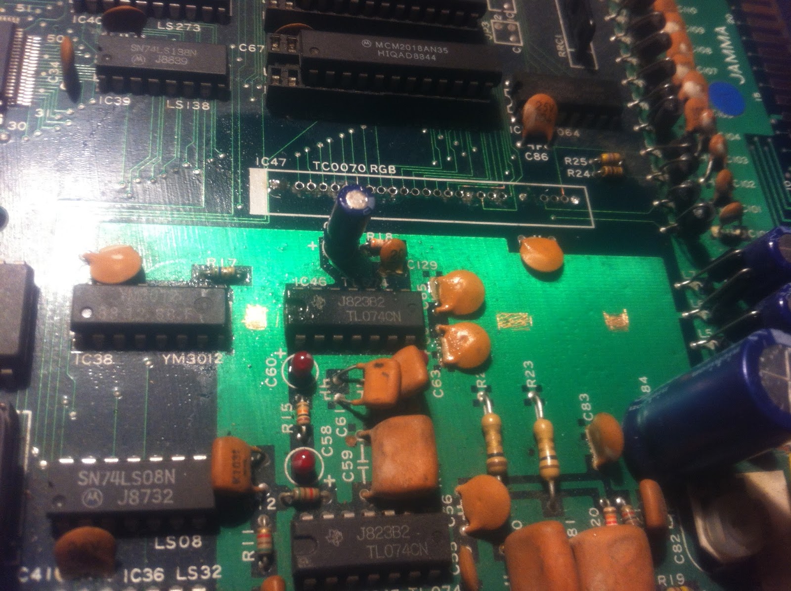
After a quick visual inspection, I found this


The smoothening cap right next to the sound chip had been crushed during transport. It would seem very likely, that this had something to do with the problem I was experiencing. All the other disc-caps for smoothening spread around the PCB is 0.1uF (code 104), so I removed the 2 broken-off pins, cleaned the holes, and installed a fresh one.


And now the music was in the right place again.


After playing a few games, I wasn't actually completely sure that music was completely right, but after inspecting an OST I found on youtube, I realised that I just have a bad memory. The music is ABSOLUTELY right now };-P

17.4.16

Psikyo Gunbird Repair Log

So, after beeing dead in the water for over a year now, Elgen is back with another one of those block rockin logs! };-P This repair was done over a year ago, but I hadn't had the time nor energy to do the write-up before now. I hope this will mark a new period of more logs to come. But please be patient here at the beginning, as I'm quite rusty };-P

<3 A Whole Lotta Love and Plz Enjoy <3
};-P E

* * * * * * * *

This story actually starts with me smashing one of my own favourite arcade PCBs... but let's start at the very beginning:

After doing this repair log about using GALs to substitute bipolar PROMs under certain circumstances, I'd really gotten interested in PLDs in general. Especially, I wanted to get enrolled in the PLD-dumping program that my dear friend porchy has going on his website JAMMArcade.net. The program is about dumping as many (mostly protected) PLDs as possible, as these are usually *not* part of the MAME ROM dumps. As the PLDs are protected, you dump them by a technique known as black-box testing: You throw all possible input at the unit under test (UUT), and record the output. While this is pretty easy for very simple logic devices like an AND-gate or similar, it's much more complex, if the UUT is able to hold internal state (i.e. FLIP-FLOPs) and/or has connection points that can be configured as both in- and outputs.
Anyway, if you build an appropriate adaptor, you can use an EPROM and "read" the PLD as a ROM. Address lines generates all the possible inputs and the data lines "record" all the output. And here we should also remember to take into account, that some of the pins can be configured as both in- or outputs. The resulting dump file can then be analyzed and we can then derive how the original equations must have been.
So I made such an adaptor, and started dumping PLDs from games in my collection that wasn't in porchys online library already. My adaptor is very quick-and-dirty and uses 2 ZIF-sockets to make it physically fit in my Needhams EMP-21, but works well. For my first dump, I started with a PAL on one of my all time favourite games: Gunbird by Psikyo.


So i popped the PAL out of its socket and dumped it in the EPROM programmer


and then inserted it into the PCB again


and hooked it up in my test bench for testing... But I got nothing but a BLACK SCREEN!!! };-( I immediately pulled the power again!

Now let's just revisit 2 of the previous pictures again side-by-side


You notice anything wrong? Let's just see them one more time then...


I had actually (clumsy as I am) inserted the poor PAL up-side-down into the socket. Of cause I tried to turn it around the right way and apply power again, but the damage was done, that PAL was toasted }:-(
Oh well, the whole purpose of dumping the PAL, was after all to be able to make a replacement. So I quickly derived the equations and programmed a GAL replacement. Slammed it into the socket and flipped the power switch full of hope. But alas... black screen! }:-( I tried verifying the GAL an extra time and also tried to dump it, but all checked out fine (as far as I remember, but more on that later).

Full of dispair, I parked the poor PCB on the shelf hoping to be able to fix it at later time...

Months went by, but suddenly one day while looking at the MAME source of another Psikyo I have in my collection, Sengoku Blade / Sengoku Ace Ep. 2, I noticed that it uses the same MAME driver. Usually this is a good indication that the games run on very similar hardware. I immediately fetched both PCBs and studied them side by side. Obviously the lay-out was not precisely the same, but there seemed to be a lot simmilarities; in particualar the both have a PAL-IC in roughly the same area...


Now just a word on the the difference between PLDs and ROMs. If you replace a ROM with one of the same type (but with different data) nothing serious happens with either PCB or the ROM. You just get errors, game will not start, graphic glitches etc. But you pop in the correct ROM afterwards, and everything is back to normal; no harm done. That is because the configuration of address and data lines, input and and outputs is always the same on a ROM regardsless of the data programmed onto it. On a PLD (ie GAL) on the other hand, you as a programmer of the device, have the power to (to some extent) define which pins should be inputs and outputs along with the logic that is programmed onto it. Two GALs programmed with different input and output configuration can therefore NOT just be safely interchanged.
But I took a chance... Aaaaaaaaaaand, MY GUNBIRD BOOTED! };-P


But as you might see on the photos, the game had now developed some other issues. Sometimes the graphics was glitchy and sometimes some of the letters was replaced by other letters or other characters. I was pretty sure, that this had nothing to do with using the PAL from Sengoku Blade, as I could influence the behavour of the glitches by flexing the PCB. This is often a sign, that some of the SMDs have pins broken off of the PCB and making poor contact.

Finding the culprits of such problems can be hard, cause you are not always able to see the cracks with the naked eye. But by pressing down on the SMDs one by one, and watching if it had any effect on screen, I found a good candidate near one of the corners; a large Psikyo custom IC.


After doing a close visual inspection of the suspecious IC, I still couldn't find anything fishy. So I decided to just reflow ALL the pins... 160 that is };-S And I really hate doing SMD soldering, cause I suck at it! I reflowed 1 side (40 pins) at a time testing in between. But after having reflowed all 4 sides, there was still no change, and I could still make the glitches go away by pressing on the custom IC. Having ruled out the large custom, I started investigeting the nearby SMDs pressing from both top and bottom at the same time and soon found that pressing on this IC


made the glitches go away. And that didn't happen when doing the same trick on the others. Luckily this one was larger and had a lot fewer pins that the big custom. And after a quick reflow of all the pins, the glitches were all gone, even when I flexed the board.

So now all was more or less good, but it still annoyed me, that I had to shift the PAL between the 2 games. So just to be absolutely sure, I tried to read the GAL I'd programmed at the beginning one last time. But for some reason it read as blank. That was strange? I tried again; same result! Now I am almost 100% that I had been dooing all the right steps of programming the GAL, but obviously something had gone wrong. Full of hope I tried to program it again with the devired equations, slammed it in the socket


and lo and behold: The game booted ever so happily! };-P

A long case was closed, and I was proud to contribute my first *real* and tested PAL-dump to the fast-growing repository over at porchys site JAMMArcade.net.

To this day, I still don't know what went wrong when I tried to program the GAL the first time... but I'm glad that all went well in the end, as both Gunbird, Sengoku Blade, and Psikyo games in general for that matter, are really some of my favourite shmups };-P

20.12.14

Taito Asuka & Asuka Repair Log

This original Taito Asuka & Asuka


I was lucky to grap real cheap on a Danish forum. The guy selling it didn't post a picture of the PCB, misspelled the name of the game, and stated that it might be a bootleg. So even though it was an auction, this game went under the radar of other forum users, and I got it for my initial cheap bid. As I later on discovered that this seller is a dirty rotten swindler, I don't feel bad about it.
Anyway, when I first received the game, it played well and was all working and fine. I decided to bring it with me to an SSKT-gathering in Næstved Denmark, as one of my friends there wanted to try it out. I don't have a car myself, so when I'm not able to get e lift with someone else, I travel by train with all my gaming goodies in a suitcase and/or backpack. Sadly Asuka&Asuka didn't quite survive the trip fully functioning. Some of the colours were frakked up


and I didn't have the time on-site to have a look at it. Upon returning home, it was just shelved, until I had a time to look at it.
Months later I decided to have a go at fixing it. I soon discovered, that this PCB suffers from the same Achilles Heel, as many other Taito games from the same period; the Taito SIL-RGB-module


And having a closer look, I could also see, that a reflow from the component side had been attempted earlier on. I found that pressing down on the package made the error go away


so I was pretty confident, that I was on the right track here.
Besides that, I also found a large cap on the loose


but I was rather sure, that this was not involved in the colour issue, so went straight on to the RGB-module.
Taito used these type of custom SIL-RGB-modules on a number of their games including i.e. Rainbow Island back in the day, and always mounted them perpendicular to the PCB, instead of making sufficient space on the PCB and bending it down onto the PCB surface. That way it's extremely flimsy and very sensitive to just the slightest bend or bump.
As an initial attempt, I tried doing another reflow from the component side, but without any luck. So I decided on desoldering the thing and mounting it properly. But when I started and gave it just i little yank while desolering, all the pins snapped clean off }:-O


I had a lot of 64-pin reduced size DIL sockets, that I bought as a mistake some time ago (wanted to use them for socketing 68000 CPUs, but didn't look closely enough at the pitch }:-S Luckily they were cheap };-P), and I decided to use 2 of these on top of each other top mount the module properly. The bottom would be soldered to the PCB, and the module would be mounted in the top one. That way the module would rise above the other components, making it easy to mount it flat.

But first the holes needed cleaning; all the old component pins were still sitting there. That proved to be a harder task than expected. Most of the pins came out pretty easy


but the holes for the 4 supply pins (2 x 5V and 2 x GND) had their vias connected to big supply planes inside (middle layers) the PCB making it very difficult to heat up the solder blobs. Also I think the supply pins themselves might be slightly thicker than the others, because they were just stuck! After having cleaned all the other holes and also broken a track on the solder side }:-S


I gave up on those 4 last holes; 5V and GND was no problem getting elsewhere nearby on the board. So I started working on the socket to be soldered onto the PCB. As there were other components on the board where the socket should be placed, I needed to cut some of the plastics so it would fit around them


I soldered some small wires on the supply pins of the socket, and also removed a bit of lacker from a big GND plane on the PCB with my Stanley knife, where the bend pins on the "other" side of the socket could attach.


I soldered in the socket connecting GND to the big GND plane "inside" the socket "walls", and 5V to a nearby cap. The pins on the "other" side got soldered to the PCB as well for proper fastening.


As a last preparation of the PCB, I replaced the electrolyte cap for an equivalent one with a smaller form factor


Now on to the top socket. I started by soldering pieces of uninsulated single core wires onto the pin-stumps on the module and then cutting them down to equal length. I then pressed the wires firmly down into the holes and caryfully bent the whole module down onto the socket


I then used hotglue to secure the module to the socket from the underside


I inserted the top socket into the other... a perfect fit };-P


After having fixed the broken track on the solder side with a piece on kynar


and reflowed the the loose cap


it was time for the big test. And lo and behold...


We have all colours back again! };-P And you can tap on, wiggle with, press down on the module etc., and the colours still stays on };-P

This game is a nice little vert shmup, but I am considering parting with it, cause the very weird sidescrolling used, kind of makes me a bit seasick when playing it };-P

4.10.14

Taito F3 Motherboard Repair Log

Finally BACK! ...from a faaar too long pause };-P
This little repair was done on-site at a gaming gathering I attended in Næstved. My friend m1chelsen, who runs a youtube channel and a blog about gaming and game collecting, has made a very nice looking consolization of a Taito F3 System. The motherboard he had gotten for free, as it might have some trouble with the controls. Also, he didn't have any games to actually test it with, so he brougth to the geeky gathering, where some other people brought their F3 carts.


It worked! ... or let's say, it almost worked. It booted up perfectly, but the down direction for player 1 wasn't responding (and Elevator Action Returns really isn't that fun without). Luckily I'd brought some basic tools with me ... just in case };-P
So after m1chelsen had freed the motherboard from the nice wooden casing


I started debugging. I followed the trace from the player 1 down pin on the fingerboard and found, that all the control inputs ends in some opto couplers (the 2 rows of white ICs; haven't really seen that before on an arcade board).


After googling the data sheet


I found that the LEDs inside have one end connected to Vcc via resistorarrays; the other end goes directly to the fingerboard. When the control is activated, the link to GND is made and the LED lights up activating the corresponding photosensitive transistor in the IC-pack.
I tested the relevant resistorpack with the multimeter


and found, the resistor for player 1 down direction broken.
Now we didn't have any spare resistor packs at hand nor a single resistor to patch on, and we wanted to play it like frakkin' now! So what to do? Hmmm think McFly, think!

....DING! (the sound of Elgen getting one his crazy ideas };-P)...

Okay, the reasoning goes like this: Due to the very physical nature of a joystick, you can never activate both up AND down at the same time. So if I connect the down-LED to the up-resistor of the array as well, they will never "use" the resistor both at the same time. So no risk of drawing too much current. I soldered in a small jumper wire on the solderside of the board


... and BAM! Dear m1chelsen was now able to ride the elevator down in Elevator Action };-P
The motherboard was put back into the nice wooden case and was played several times during the weekend. This closes the case };-P

More blog posts is on it's way soon ... promise! Also remember, that you are also able to follow ElgensRepairs via Facebook, Twitter, Instagram.

<3 Love };-P Elgen <3

16.5.14

Incredible Technologies Strata Bowling Repair Log

About a year a year ago, I started becoming a Wednesday night regular at Chassis Arcade on Østerbro, Copenhagen. It's located in a basement in Faksegade, and on Wednesday nights, it's THE place to be. It's always packed with lovely and friendly people, there's funny contests, people are playing, talking and having a brewsky or two, and after the arcade closes at 10 o'clock, we hit a nearby pub and have a few drinks. Ever since my first Wednesday there, a machine had been standing in the corner turned off. It was a Strata Bowling; not the one with the trackball depicted in the KLOV link, but actually the version that uses a real cue ball and IR-sensors to detect the direction and speed of the ball being thrown. The game is really cool, and behind the brand Strata actually stands Incredible Technologies that later made some very famous titles including the Golding Tee series.
The problem with this poor machine was, that it kept blowing the fuse on the logic board. Chriss and Julian (the owners of Chassis Arcade) had tried a few things, but couldn't get it to work, so they asked me if I'd have a look at it. And that's how the PCB ended up on my test bench.


The edge connector is (besides the controls) JAMMA compatible, so I didn't need to make an adaptor. I didn't have any fuses with the correct form factor (the big ones), so I started by just hooking up one the small ones using some crocodile test wires


however the game wouldn't start at all. Pretty soon I found out why


the poor board didn't get enough juice; I guess those test wires has way too much resistance in them. On the first picture I measure before the fuse, and on the second one after. So I made an alternative solution


I piggy backed the little fuse on top the big blown one. And now the game actually booted up... no blown fuse or anything!


I heard a fine start-up jingle, but the display wouldn't sync properly. I have had such problems before, due to the fact that I'm using a Commodore monitor for test instead of a real arcade monitor, so I just assumed that this was one of those cases as well; more on that later...
The board now seemed to be booting to some extend, so before I returned it to Chriss and Julian, I decided to see if it might have any other obvious errors. A cell battery should always alert a conscientious arcade repper, and this was no exception


The battery is 3V, but gave a reading of 0.27V. So it was desoldered. I didn't have a replacement at that time, so I made this rather crude solution for a start


just using 2 standard AAA batteries in series connected with wires. Now I was pretty confident, that the problems had been fixed, and that the syncing wouldn't be a problem once it got connected to a proper arcade monitor. So I proudly brought it back to the arcade...

After some time, Julian found time to connect it in the cab only to find, that the piggy backed fuse blew right away }:-( So home to me it went again.

It now sat on the shelf for a couple of weeks, while I was doing some other stuff. Amongst that, I had to hook a Q*bert Qubes, that uses positive horizontal and vertical sync instead of negative composite (as pretty much all JAMMA boards use), in my test bench. While googling on how to convert the syncing signal to composite negative sync, I learned that some PCBs actually has a dip switch setting to switch between positive and negative sync. Hmmmm, I wonder!?.... try looking at page 11 in the manual (in the paragraph "SYNC").
So I grabbed the board from the shelf, flipped SW1, made another crude "solution" to the fuse problem


(plz don't try this at home), and applied power


I couldn't get the game to actually start due to the "CUE BALL IS MISSING"-detection, but when I hit the service button, it bought up the service menu


and I was able to playback some of the in-game cut-scenes (for strikes and so on) from there


I wasn't too proud of the battery "solution" that I had come up with, so while I had the board back at the bench, I decided to make it a little bit nicer. I had this old PC-motherboard in the scrap pile. It had a battery of a different form factor, but still 3V... and it was placed in a battery holder.


This type of batteries can be purchased in any bigger supermarket for about 10DKK (~$2) a piece, so that was a perfect solution. So desoldered the holder and attached a wire because of the different form factor


and soldered it onto the board


I can see that it works perfectly, as when I take out the battery, the game boots with a message that the battery is dead. But when it's installed, it saves the settings I've made in the service menu.

The last thing to get settled, was the issue with the blowing fuse. So I tried using one of the small again, and the board booted perfectly. However, when I tried to boot it again the next day, the fuse blow right away.
And THEN it struck me! I had been using fast (in danish: flink) fuses. These are designed to blow at the moment the current gets too high. Slow blow (in danish: træg) fuses however, can withstand a much higher current than what they are rated for, for a short period of time. Very close to the fuse are a couple of rather big electrolyte capacitors. When I booted the board with the "wired" fuse, these would get charged just fine, but when trying with the fast fuse, it would blow right away, because of the high current this charging generates. I couldn't find any documentation anywhere if this fuse should be fast or slow blow, but after seeing that the board runs just fine with a fast fuse once the caps are charged, I'm not in doubt.
So on my way to the arcade that day, I bought a 10 pack of slow blows (in the right form factor), as I didn't have any, and handed them over along with the PCB. About a week later, Chriss and Julian sent me this awesome video


The 2 jolly arcade owners speaks danish in the video, but to recap they're telling, that the game now seems to work just fine, but that they are missing a ball of the right size. Should you, good reader, know anything about what ball to use, plz leave a comment.

So this ended up being more of a piece of detective work and hardly any real repairing. But that's how it is some times, and I'm just happy that it works, and I'm really looking forward too trying this game out };-P

(Don't forget to swing by my Facebook-page and like it to get more frequent updates than just following the blog.)