About me

My photo
Vanløse, Copenhagen, Denmark
Mathematician. Working programmer/system developer. Nerd. Married. Father of 3.
Showing posts with label Taito. Show all posts

20.12.14

Taito Asuka & Asuka Repair Log

This original Taito Asuka & Asuka


I was lucky to grap real cheap on a Danish forum. The guy selling it didn't post a picture of the PCB, misspelled the name of the game, and stated that it might be a bootleg. So even though it was an auction, this game went under the radar of other forum users, and I got it for my initial cheap bid. As I later on discovered that this seller is a dirty rotten swindler, I don't feel bad about it.
Anyway, when I first received the game, it played well and was all working and fine. I decided to bring it with me to an SSKT-gathering in Næstved Denmark, as one of my friends there wanted to try it out. I don't have a car myself, so when I'm not able to get e lift with someone else, I travel by train with all my gaming goodies in a suitcase and/or backpack. Sadly Asuka&Asuka didn't quite survive the trip fully functioning. Some of the colours were frakked up


and I didn't have the time on-site to have a look at it. Upon returning home, it was just shelved, until I had a time to look at it.
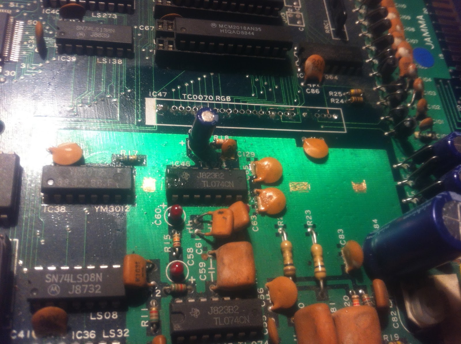
Months later I decided to have a go at fixing it. I soon discovered, that this PCB suffers from the same Achilles Heel, as many other Taito games from the same period; the Taito SIL-RGB-module


And having a closer look, I could also see, that a reflow from the component side had been attempted earlier on. I found that pressing down on the package made the error go away


so I was pretty confident, that I was on the right track here.
Besides that, I also found a large cap on the loose


but I was rather sure, that this was not involved in the colour issue, so went straight on to the RGB-module.
Taito used these type of custom SIL-RGB-modules on a number of their games including i.e. Rainbow Island back in the day, and always mounted them perpendicular to the PCB, instead of making sufficient space on the PCB and bending it down onto the PCB surface. That way it's extremely flimsy and very sensitive to just the slightest bend or bump.
As an initial attempt, I tried doing another reflow from the component side, but without any luck. So I decided on desoldering the thing and mounting it properly. But when I started and gave it just i little yank while desolering, all the pins snapped clean off }:-O


I had a lot of 64-pin reduced size DIL sockets, that I bought as a mistake some time ago (wanted to use them for socketing 68000 CPUs, but didn't look closely enough at the pitch }:-S Luckily they were cheap };-P), and I decided to use 2 of these on top of each other top mount the module properly. The bottom would be soldered to the PCB, and the module would be mounted in the top one. That way the module would rise above the other components, making it easy to mount it flat.

But first the holes needed cleaning; all the old component pins were still sitting there. That proved to be a harder task than expected. Most of the pins came out pretty easy


but the holes for the 4 supply pins (2 x 5V and 2 x GND) had their vias connected to big supply planes inside (middle layers) the PCB making it very difficult to heat up the solder blobs. Also I think the supply pins themselves might be slightly thicker than the others, because they were just stuck! After having cleaned all the other holes and also broken a track on the solder side }:-S


I gave up on those 4 last holes; 5V and GND was no problem getting elsewhere nearby on the board. So I started working on the socket to be soldered onto the PCB. As there were other components on the board where the socket should be placed, I needed to cut some of the plastics so it would fit around them


I soldered some small wires on the supply pins of the socket, and also removed a bit of lacker from a big GND plane on the PCB with my Stanley knife, where the bend pins on the "other" side of the socket could attach.

I soldered in the socket connecting GND to the big GND plane "inside" the socket "walls", and 5V to a nearby cap. The pins on the "other" side got soldered to the PCB as well for proper fastening.


As a last preparation of the PCB, I replaced the electrolyte cap for an equivalent one with a smaller form factor


Now on to the top socket. I started by soldering pieces of uninsulated single core wires onto the pin-stumps on the module and then cutting them down to equal length. I then pressed the wires firmly down into the holes and caryfully bent the whole module down onto the socket


I then used hotglue to secure the module to the socket from the underside


I inserted the top socket into the other... a perfect fit };-P


After having fixed the broken track on the solder side with a piece on kynar


and reflowed the the loose cap


it was time for the big test. And lo and behold...


We have all colours back again! };-P And you can tap on, wiggle with, press down on the module etc., and the colours still stays on };-P

This game is a nice little vert shmup, but I am considering parting with it, cause the very weird sidescrolling used, kind of makes me a bit seasick when playing it };-P

4.10.14

Taito F3 Motherboard Repair Log

Finally BACK! ...from a faaar too long pause };-P
This little repair was done on-site at a gaming gathering I attended in Næstved. My friend m1chelsen, who runs a youtube channel and a blog about gaming and game collecting, has made a very nice looking consolization of a Taito F3 System. The motherboard he had gotten for free, as it might have some trouble with the controls. Also, he didn't have any games to actually test it with, so he brougth to the geeky gathering, where some other people brought their F3 carts.


It worked! ... or let's say, it almost worked. It booted up perfectly, but the down direction for player 1 wasn't responding (and Elevator Action Returns really isn't that fun without). Luckily I'd brought some basic tools with me ... just in case };-P
So after m1chelsen had freed the motherboard from the nice wooden casing


I started debugging. I followed the trace from the player 1 down pin on the fingerboard and found, that all the control inputs ends in some opto couplers (the 2 rows of white ICs; haven't really seen that before on an arcade board).


After googling the data sheet


I found that the LEDs inside have one end connected to Vcc via resistorarrays; the other end goes directly to the fingerboard. When the control is activated, the link to GND is made and the LED lights up activating the corresponding photosensitive transistor in the IC-pack.
I tested the relevant resistorpack with the multimeter


and found, the resistor for player 1 down direction broken.
Now we didn't have any spare resistor packs at hand nor a single resistor to patch on, and we wanted to play it like frakkin' now! So what to do? Hmmm think McFly, think!

....DING! (the sound of Elgen getting one his crazy ideas };-P)...

Okay, the reasoning goes like this: Due to the very physical nature of a joystick, you can never activate both up AND down at the same time. So if I connect the down-LED to the up-resistor of the array as well, they will never "use" the resistor both at the same time. So no risk of drawing too much current. I soldered in a small jumper wire on the solderside of the board


... and BAM! Dear m1chelsen was now able to ride the elevator down in Elevator Action };-P
The motherboard was put back into the nice wooden case and was played several times during the weekend. This closes the case };-P

More blog posts is on it's way soon ... promise! Also remember, that you are also able to follow ElgensRepairs via Facebook, Twitter, Instagram.

<3 Love };-P Elgen <3

7.4.14

Bubble Bobble Lost Cave & REDUX on same bootleg PCB

About a year ago, i managed to snap up a cheap defective bootleg Bobble Bobble that I fixed and installed the REDUX ROM set on. That works fantastic, but another exciting project is Lost Cave, that originally released on December 11, 2012. It's a very ambitious fan project made by the 2 good fellows Bisboch & Aladar and consists of 100 "new" levels for the original arcade game. "New" are in quotes, as it's actually the best levels from various ports, that have been backported to the original arcade platform. Along with that, it introduces a lot of new elements for example on the graphical side. The original release from 2012 only ran on original Taito hardware (and MAME), but when the authors discovered REDUX, they got inspired to try and do a bootleg-PCB version as well; and as of Lost Cave v1.2 (December 11, 2013) it also runs on bootleg boards (the kinds without a 68705; so the same criterion as running REDUX).

I downloaded the Lost Cave (bootleg) ROM set and installed it on my board, and it worked like a charm; jawsome game! };-P Now Lost Cave is a whole new game with new levels and stuff; the original levels are not present in the game anymore. So I started thinking about how I could find an easy way to run both Lost Cave and REDUX on my board, without having the fuzz of swapping the ROMs every time.

The first thing to notice is, that all the ROMs on the board are 27256


Next thing to notice is, that EPROMs in the 27-series comes in "clusters" of form factors given by the type of DIP packages. So ie 2716 and 2732 are both DIP24, whereas 2764, 27128, 27256, 27512 are all DIP28 and so on. Now if you compare the pinouts of 27256 and 27512


you'll find, that they are almost identical with the exception of pins 1 and 22. The 27512 uses pin 1 as the extra address pin and have pin 22 double as both Output Enable (in reading mode) and Programming Voltage (in programming mode). Now pin 22 we don't have to worry about, as the EPROM will only operate in reading mode on the board. But pin 1 will allow us to switch between the upper and the lower 256K bits of the EPROM. This scheme is often referred to as bank switching (at least when it's is done runtime, anyway), as you divide the address space of the ROMs into two separate banks that you can switch between.
Now to pull this through, I first had to identify the union set of all the ROMs that has to be swapped to go from straight bootleg to either REDUX or Lost Cave. Now the REDUX are marked with bow ties and the Lost Cave are marked with fezzes


...the union set is of cause just all the marked ROMs };-P. Please note, that on other bootlegs, these ROMs might have very different numbers/id's, so it's the position that's the important thing here.

Next I started doing the plumbing for the bank switching. First of all, I would need an ON-ON switch with +5V on one pole and GND on the other; the middle will then be the "bank switcher". I just happened to have a bag of tiny ON-ON switches stocked that fits into 3 successive holes on a DIL, so as bootlegs often has a lot of unused holes, I easily found some usable ones to clean up.


and installed the switch


Next, the wires got soldered on on the solder side


The red wire is +5V, the unisolated is GND, and the blue is the bank switch-wire.
Now on the main PCB, 3 of the 4 ROMs to be swapped (the 3 ones on a line), already had pin 1 tied to a GND-rail individually, so these connections had to be cut of course.


These are marked with 3 red arrows; I also accidentally (it was late at nite }:-S) cut the connection to pin 2 on the middle ROM (blue arrow). So that's why there is also a piece of red kynar to patch this up on the next pic showing how the pin 1's are connected to the bank switch-wire.


As you can see, the blue switch-wire ends at the ribbon cable connector


That's because the switch-signal needs to be passed on to the secondary board. And as I didn't want any extra wires (that would have to be desoldered every time the board is taken a part), I choose to hijack one of the many GND wires on the ribbon cable (notice the cut). Now that was all the plumbing needed on the primary board. The secondary board was actually easier. Here, all the pin 1's on the ROMs was already interconnected, with a GND-connection in one end, and a connection to a resistor array in the other end. So only 2 cuts on the component side needed to be made


And then of cause, the connection to the hijacked ribbon pin had to be cut and connected


The last thing needed to pull this off, was the actual ROMs. Now as I'd dumped all the ROMs during the repair, I had a full set of REDUX ROM files for my board. Also, before I even started, I'd checked that Lost Cave v1.2 would actually run on my board, so I had a full set of files for that too. So it was only a matter of combining the two sets, for each ROM that needed to be swapped. This is easily done ie in a Windows cmd prompt with the command
~> copy /b rom1 + rom2 combined_rom
for every pair of ROM files; of cause taking care, that the files from the same set were always first/last };-D

So I replaced all the 27256-ROMs to be swapped with the just programmed 27512-ROMs and fired up the board full of excitement };-P


Now that's just puuuure awesomeness, ain't it? };-P

As a last thing in this post, I wish to mention, that I've recently created a Facebook page, that'll make it a bit easier to follow the blog. Here I'll post every time I make a new blog post, but also make minor posts about progress of current projects etc. I welcome you to visit, and 'like' if you wish to be updated on the stuff I do.

A whole lotta love from Yours Truly };-P

28.3.13

Taito Bubble Bobble Bootleg Repair Log & REDUX

About a month ago, my dear friend porchy made this post on his blog. Now it is 'common knowledge' in the arcade society, that bootlegs of Taitos Bubble Bobble doesn't play like the original. The reason why, is that the original board has a custom chip (know as the PS4...the one featuring a picture of Bub from the game on the silk screen) that shares the SRAM with the main CPU (a Z80). The PS4 is a 6800-based CPU also containing some memory in the form of ROM. Every now and then, the PS4 changes some bits and pieces in the SRAM, so that certain events occur in the game. The things that most people notice as wrong is enemy movements and that the sequence of the EXTEND-letters is not randomized.
The bootleggers back in the days, were not able to extract the program data from the PS4, so they tried to deduce the data by the use of a technique known as 'blackboxing'. You throw a lot of different input at the chip and then record the output. You then analyze both the input and output and try to make your own program do the same as the chip. They did that by exploiting some unused interrupt cycles of the main CPU to execute this PS4-emulation. However they didn't get it quite right.
But recently MAMEDev succeeded in reading the program from a PS4 by using a technique known as decapping. In short, you cut off the top of the IC, look at the silicon plate under a strong microscope, and manually read every single bit. This way they made it possible to make a perfect emulation of the original game in MAME.
Now this is where joaoljr, a brazilian member on the arcadeotaku forum, got the idea that it might be possible to make all those old bootlegs play correctly! He took the 6800 assembler-code extracted from the PS4 via decap, rewrote it to Z80 assembler, and excecuted it in the spare interrupt cycles of the main CPU just the like bootleggers back in he days. He calls the project REDUX, and you can read all about it in this thread.

Phew, that was a long intro...but when I had read all this, I started looking for a cheap bootleg, and soon found an untested one from a french seller on evilBay. From the auction photo, I made sure, that this was indeed a REDUX-able type of bootleg ie doesn't have an 68705 MCU.


The auction closed at 29.90EURO with a shipping price to Denmark of 13.90EURO; so all-in-all ~45EURO for an untested bootleg Bobble Bobble...sweet! };-P

When the board arrived, I did the usual visual inspection. It was obvious that this board had been made in a rush; some components had not been pressed correctly into the holes, before the board went into the flowsoldering machine (this is the worst example)


However all the pins made fine contact, so if I could get it up and running, I didn't bother. Also some rather ugly mod/repairs had been done on the secondary board


But again, if I could make it work, why bother. One thing about this board looked extremely strange though


Notice that the two ribbon connectors doesn't match up. Also notice that both the upper and lower PCB has the parts side facing up. This is very rare on arcade boards, as they are usually back-to-back/front-to-front. I tried to check for contact between GND on the edge connector and GND on an IC on the secondary PCB with my multimeter and found none. Hmmm, this started to smell bad };-S I removed the legs and flipped the secondary board 180 degrees so the PCB was now back-to-back, and viola


suddenly the two ribbon connectors matched up. And I checked for connection between GND on the two PCBs, I got a fine beep };-P Now I was extremely happy, that the seller didn't test this board, as the consequences could have been disastrous. My only hope was, that he was telling the truth.
Next, I started dumping all the ROMs on the board, but when I got to the one labeled "2", I found this


and ofcause I was unable to read it in the Top. Now it is actually possible to transplant pins from an old IC, if there is just a tiny bit of the pin left, so I tried doing that


and was now able to read it in the Top. All the ROMs validated against MAME };-P Next step, was to actually test the board. I found the pinout at mikesarcade.com and threw together a QAD adaptor with only power, video, and sound.


The board booted up just fine


however the colours looked a bit strange. Either the pinout I had found was wrong, or this was a unique type, where blue and red crossed. I switched the two wires, and got this


Perfect colours and the sound was fine too. Quickly I hooked up the rest of the wires


and was able to play a test game...both 1P and 2P worked perfectly...sweeeet! };-P

Now for the REDUX-part. I downloaded the package with the prepatched ROMs (linked from the thread), and programmed them onto 3 27C256 EPROMs. Slammed them into the board (I have to make some nice custom stickers };-P),


and fired her up


Meesa liiiike dat!!! Haven't played it to the end yet, but it seems to play just flawlessly };-P REDUX FTW!!! A special thnx to joaoljr for the big effort.