This board, a bootleg of Capcoms Last Duel (a vertical shooter with the subtitle "Inter Planet War 2012"; so ofcause I HAD to get it fixed before entering the new year };-P), I got in the same batch as Missing in Action and Fighting Soccer. The hardware is pretty standard and consists of two PCBs connected with ribbons.
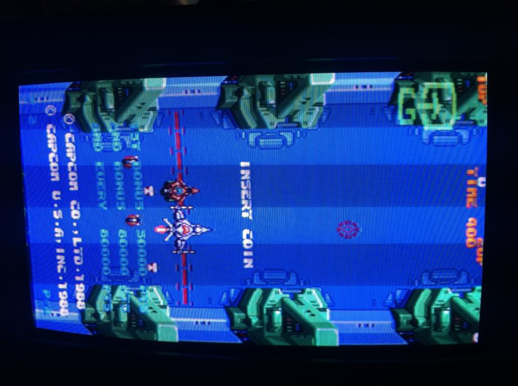
When first plugged in, what I saw was this:
(a screen filled with garble...or so I thougth, but more on that later...)
I started by piggybacking the SRAMs on the primary PCB
and when doing so on an 6116, I got this screen; certainly a change.
But when desoldring, it tested good in the Top2005+, so it went back in.
It was then I discovered, that when doing a continuity test between +5V and GND on the egde connector, I got a beep. Switching to Ohms on the multimeter I saw that the impedance was about 50Ohms. That somehow didn't seem rigth, and I spend most of an evening trying to find out what was shortening the two. That included inspecting the many former repairs done on the main PCB (or maby just a consequence of it being a bootleg; the pics below shows only some of them). I desided on removing and redoing them one by one, each time trying to boot the board when they were off. But it didn't change a thing.
It was then I got the brilliant idea of trying to do the same continuity test on some working boards, and found that at least 2 of the 4 boards I tried had less than 70Ohms of impedance between +5V and GND. I then stopped chasing that ghost...
But now suddenly the screen looked VERY diffenrent (sadly I didn't catch a pic of it). Turning the board around and inspecting it, I saw that the reset-pin had been knocked off the main CPU, mainly because of the cap that was soldered onto it.
Here the damage is seen with the very simple bootstrap-circuit removed.
Mainly inspired by
this rep log by Womble where he fixes a custom SMD IC with knocked of pins, I dug up my Dremel and started carving my way through the casing of the 68000.
Switched to a carving head a little less rough when I got close to the track.
And finally I found shiny metal };-D
soldered a wire on, and fastened it with drops of SuperGlue.
And this is the final result with the bootstrap circuit back in place. Now I had the usual screen of gable; ie status quo };-S
It was then I discovered, that this was NOT just a screen full of garble (try and have a scoll up and look at pic2 again!); this was actually the initial self-test booting up and trying to communicate with me. It reads: "WORK RAM : OK" and the next line was: "V R A M : NO GOOD". Aha! now I had something.
So flipped the board around to look at the SRAMS in graphics section. This is two of the SRAMS on the secondary PCB, and if you have a look just to the left of them, you see 2 usual suspects...Fujitsus (the two 245).
After a quick inspection I found that the secondary PCB had 9 Fujitsu-245 all in all. As I just happend to actually have a tube of TexasInstruments equivalents, I desided to desolder them all, fit sockets, and install new ones.
They all tested good except for number 3 from the left in the pic above.
and having a closer look, it didn't look good (notice the white "thing" on the right half of it...it looked like it had been very hot at some point).
After having installed all new TexasInstrument-IC's, the self test wrote "V R A M : OK" aaaaaand...
The board booted up! };-D
(Here are the 9 Fujitsus ready for the bin.)
The next problem to adress was: No sound! I tried the "finger test" on the amp, but there was not even a small hiss from the speakers. So googled the pinout for the amp; and hit the output (1) with the scope probe...
...and saw this (pic below). Now this looked alot like sound to me. So chased the signal downstream til the cap marked with 2, and found the signal at the other side as well. From there it went back to the amp (either feedback or bootstrap; can't remember which), but also to the cap marked with 3. When hitting the other side of that cap with the scope, I got a total flat-line.
Replaced the cap with a new one, and it brought back sound.
Now the board was all good to go. So I connected the 2 PCBs with the legs again, I hooked up my SuperGun/testbench to my vertical tv for a test game, and then Johannes aka Elgees[2] woke up and needed my comfort....
After about 30minutes of constant singing and comforting, I returned and saw that I had left the game running. But sadly it wasn't running anymore. The screen that met was the one below, and it was frozen };-S
Turned the power off and on again and got this: "SCROLL 2 : NO GOOD".
Now I didn't know where to find the scroll2-RAM, so I grapped my "poker" (that is what I call this little simple but very handy tool; home-made from an old multimeter probe and a crocodile clip. You attach the clip to either +5V or GND and is then very easily capable of pulling different enable-pins on ICs high or low.)...
...and found the scroll2 was the two SRAMs to the left in the pic below. By accidently pressing down on the PCB in that area, I also saw, that I could provoke the scroll2-error in the self-test. So off the legs went again (moan!).
It seemed I'd been a bit too hasty, when replacing them 245's with sockets, as I'd forgotten to solder one of the pins. Fired up the iron, soldered the pin, and the scroll2-error was gone even if I pressed down on the PCB. One more board taken out of it's coma };-)
The game is actually a quite nice shmup once you get past the first stage, so I finish off this log with some pics from stage2, which has some really nice graphics; enjoy! };-P